Skip to content

FIG. 07 — DOCUMENTATION

The Project in Pictures

Visualise the project materialize through successive stages of development and how a idea transforms into a tangible outcome.

FIG. 07A — VIDEO

The Project in Motion

Three short vertical demonstrations of the prototype in use.
  • VIDEO 01
  • VIDEO 02
  • VIDEO 03
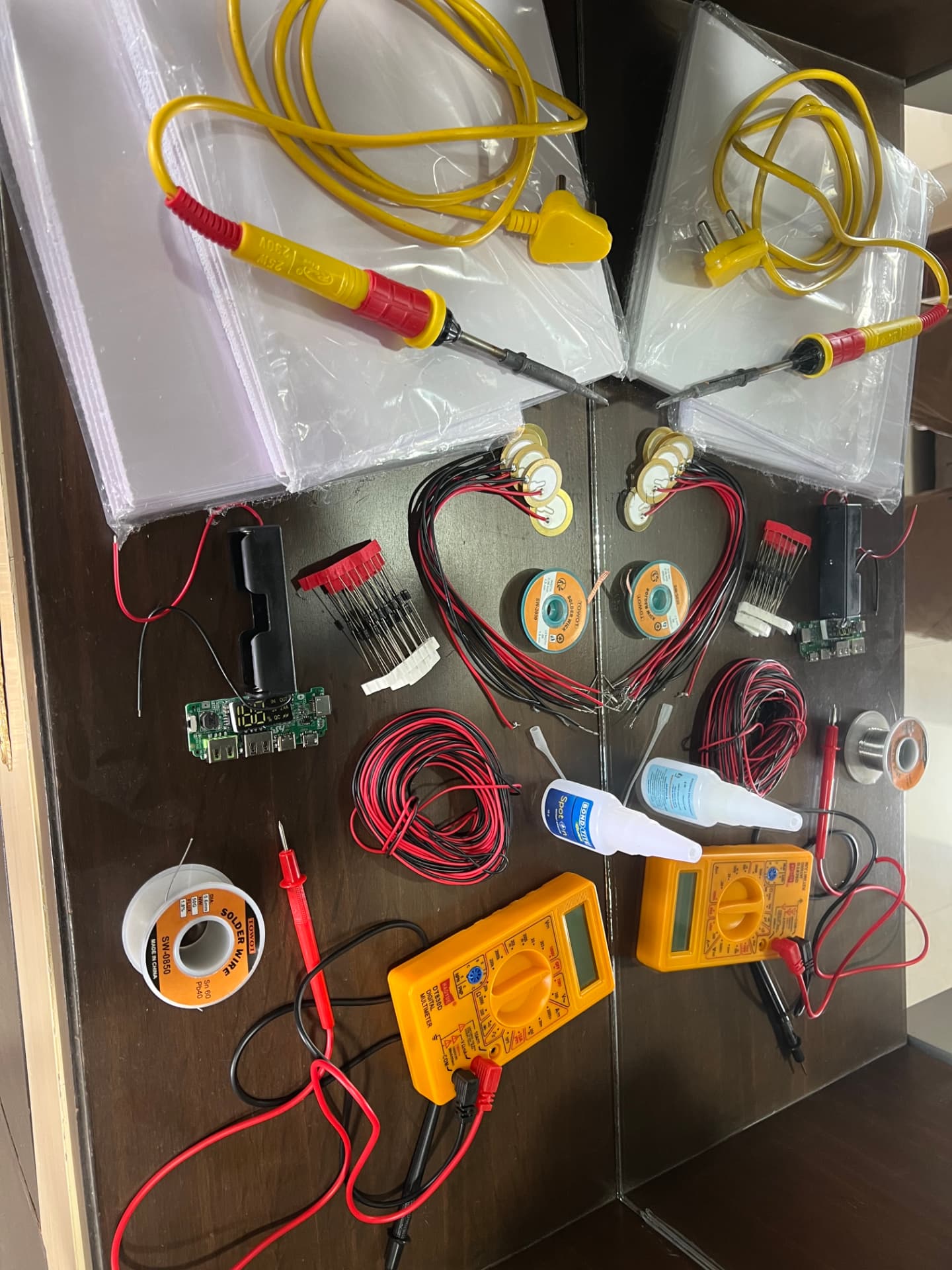
  • Tools and components laid out before assembly: soldering irons, two digital multimeters, solder, adhesive bottles, piezo sensors and power bank modules.
    MATERIALS
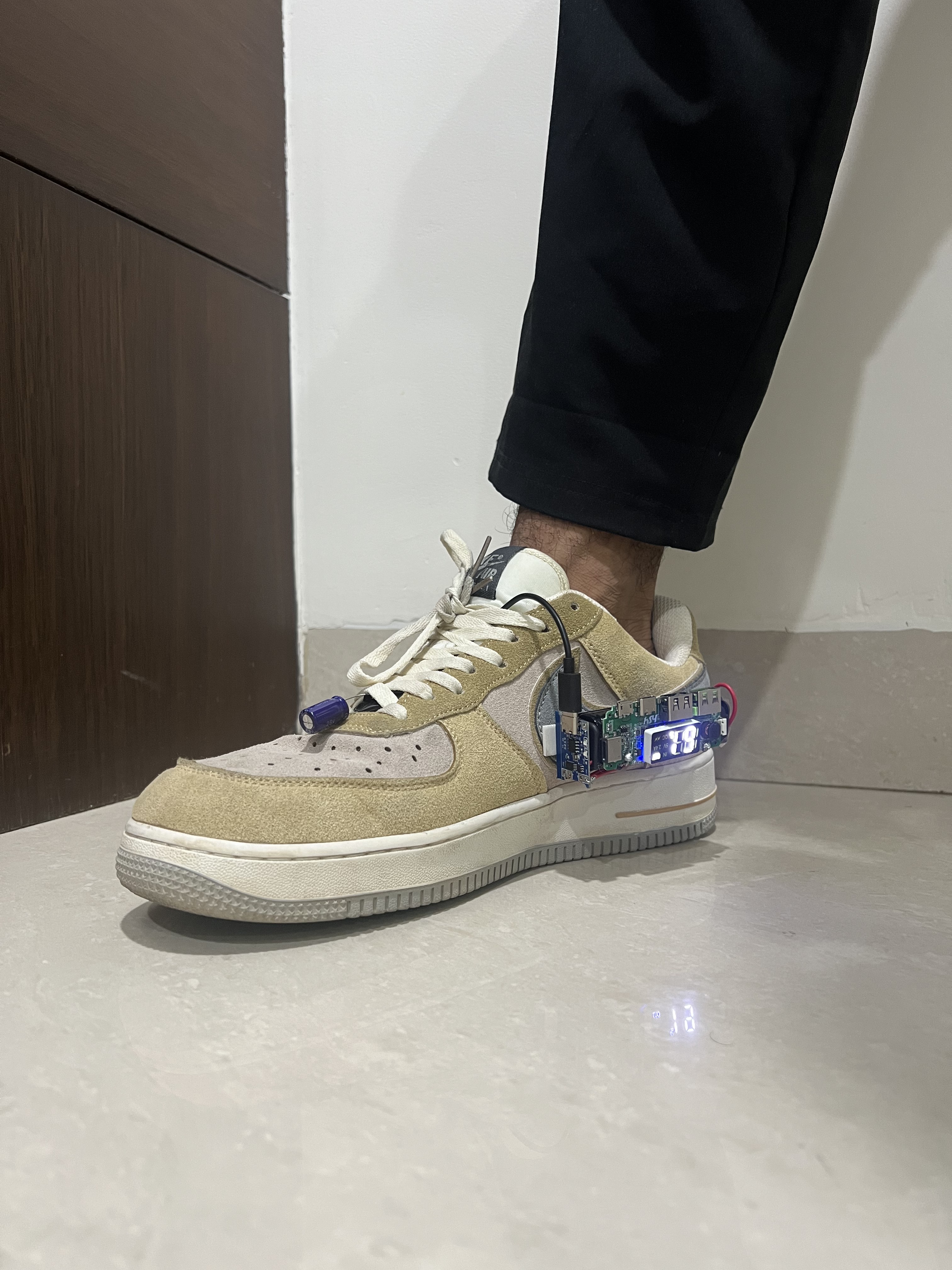
  • A person's foot in a tan Nike sneaker wearing the prototype: a blue capacitor laced across the toe, wires running to a blue board and a green power bank board whose display reads 79.
    FINAL DESIGN
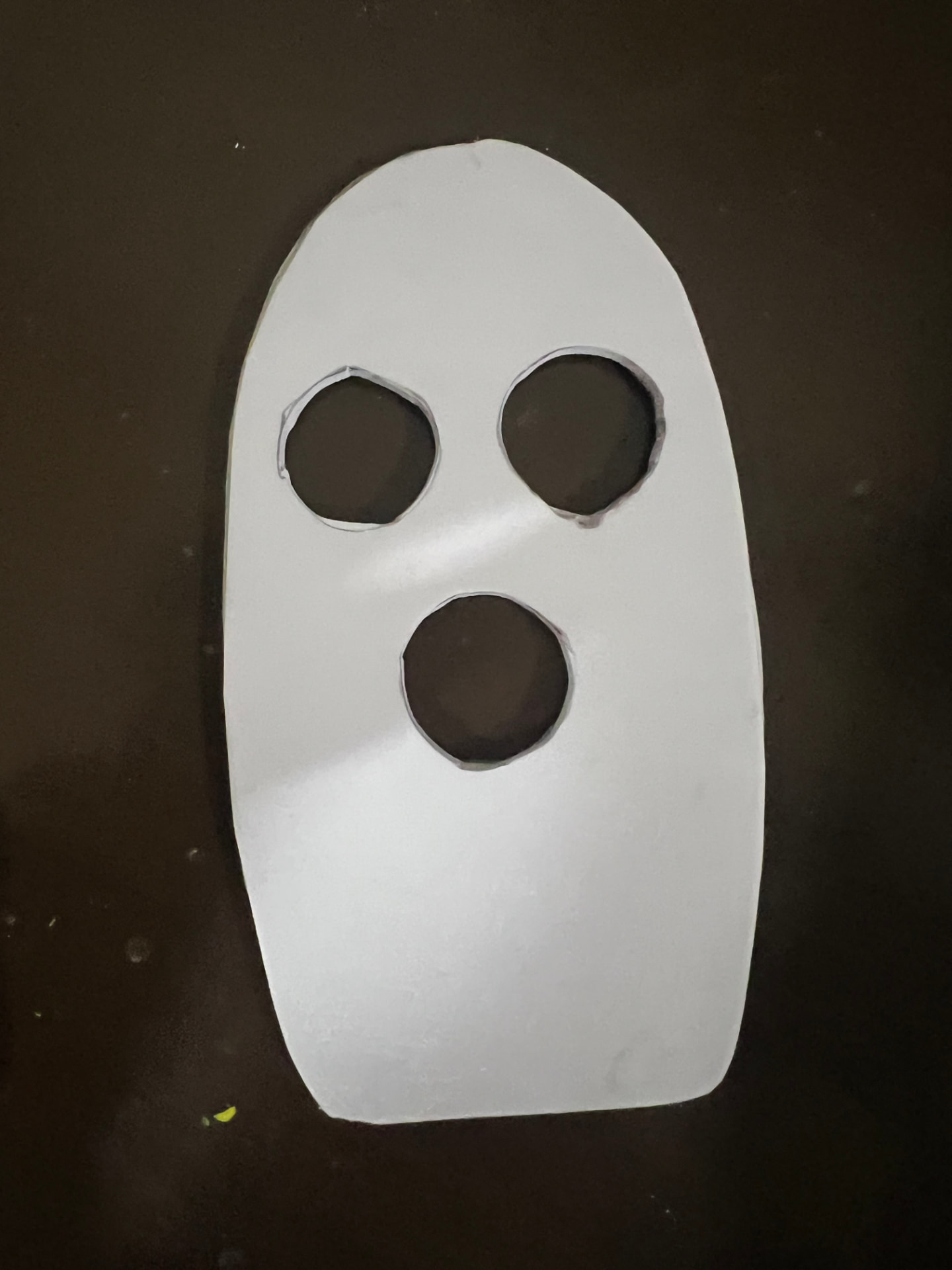
  • A white plate cut to shape with three circular holes, resting on a dark surface.
    ACRYLIC PLATES
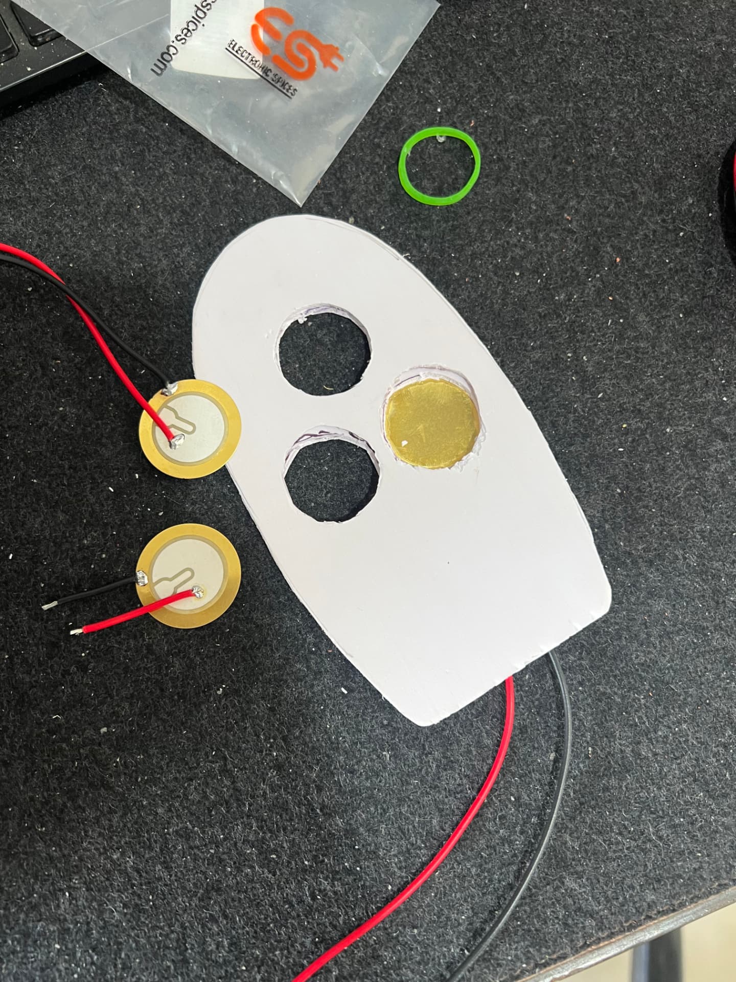
  • A brass piezo sensor fitted into one of the holes in the white plate, with red and black wires being added.
    PIEZOELECTRIC TRANSDUCERS
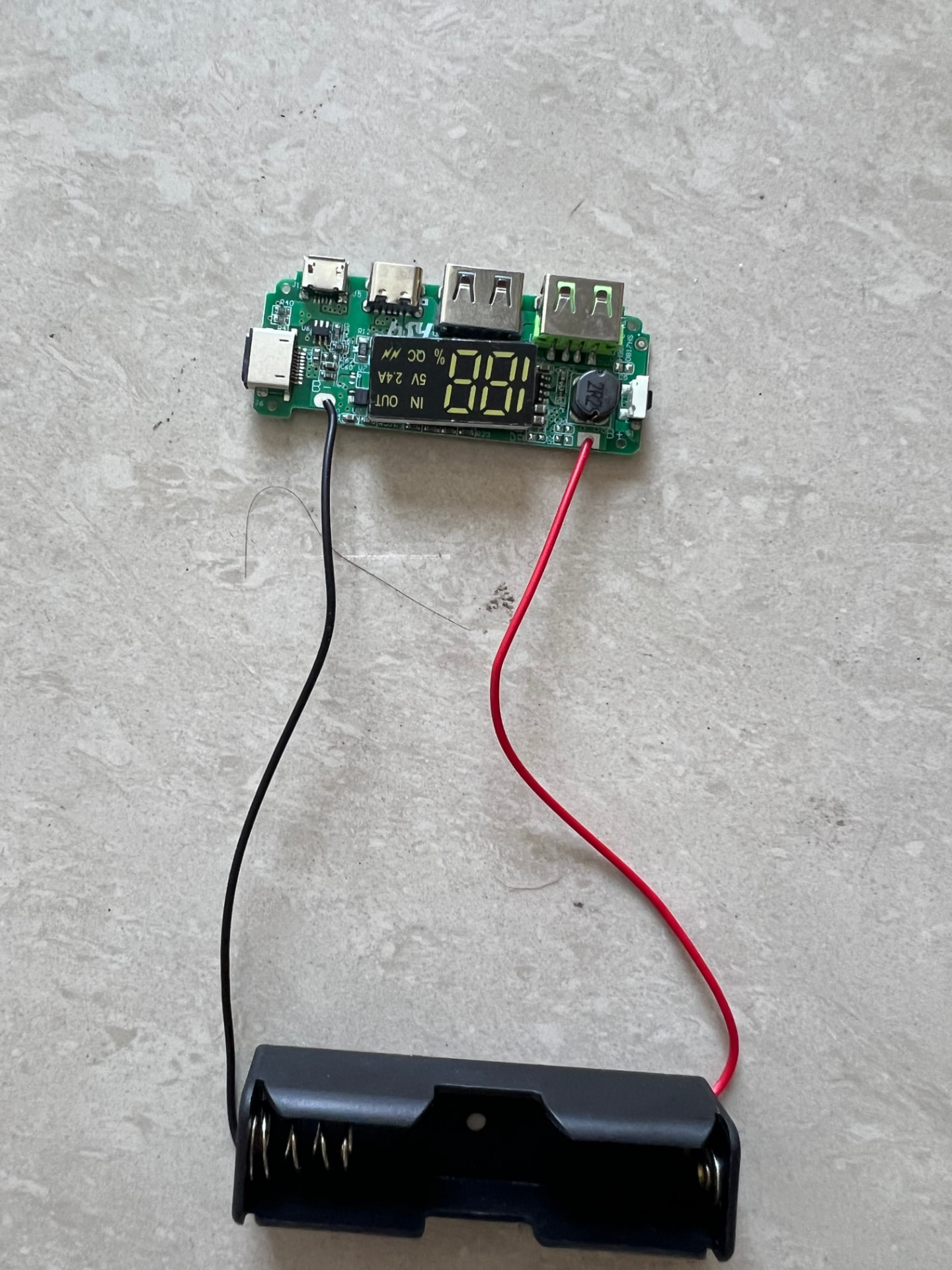
  • A power bank circuit board showing a charge reading of 100, wired to a black battery holder.
    POWER BANK MODULE AND BATTERY CASE
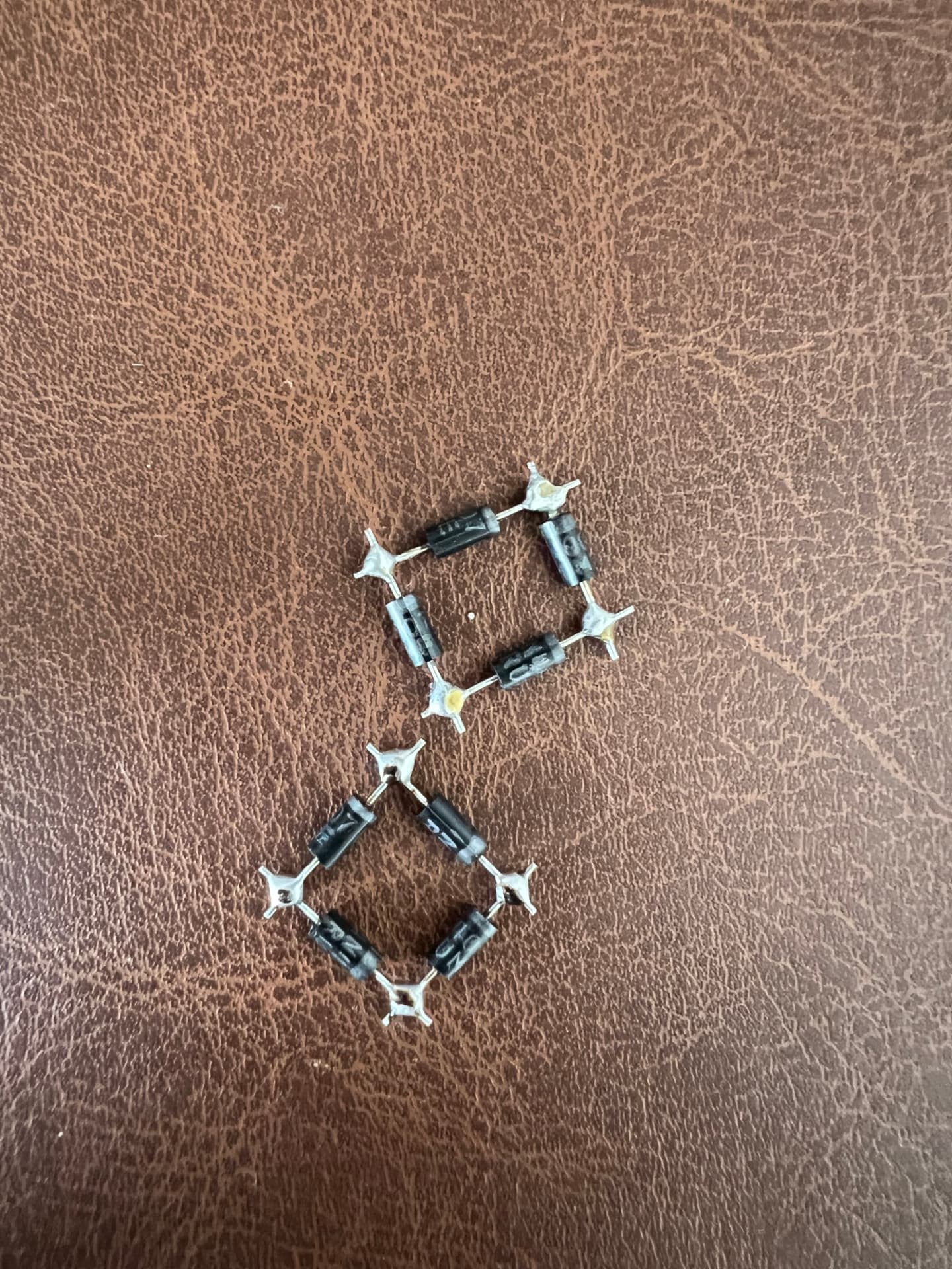
  • Two hand-soldered diode bridges made from four rectifier diodes each, resting on a brown surface.
    FULL-WAVE BRIDGE RECTIFIER USING DIODES
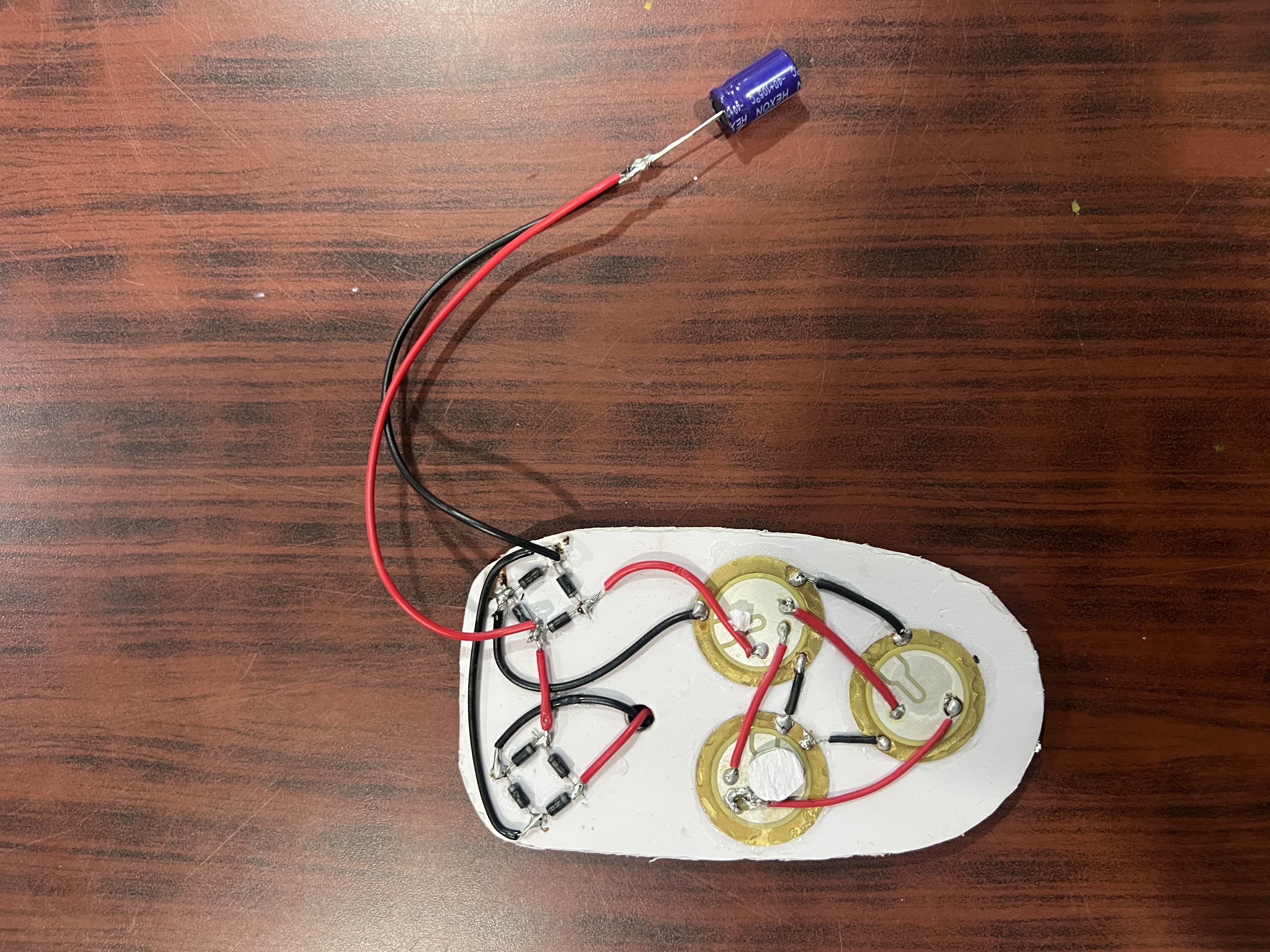
  • Close-up of three brass piezo discs glued to the white base, wired to two bridge rectifiers made from eight diodes, with a blue capacitor on the output wires.
    CAPACITOR TO STORE CHARGE PRODUCED
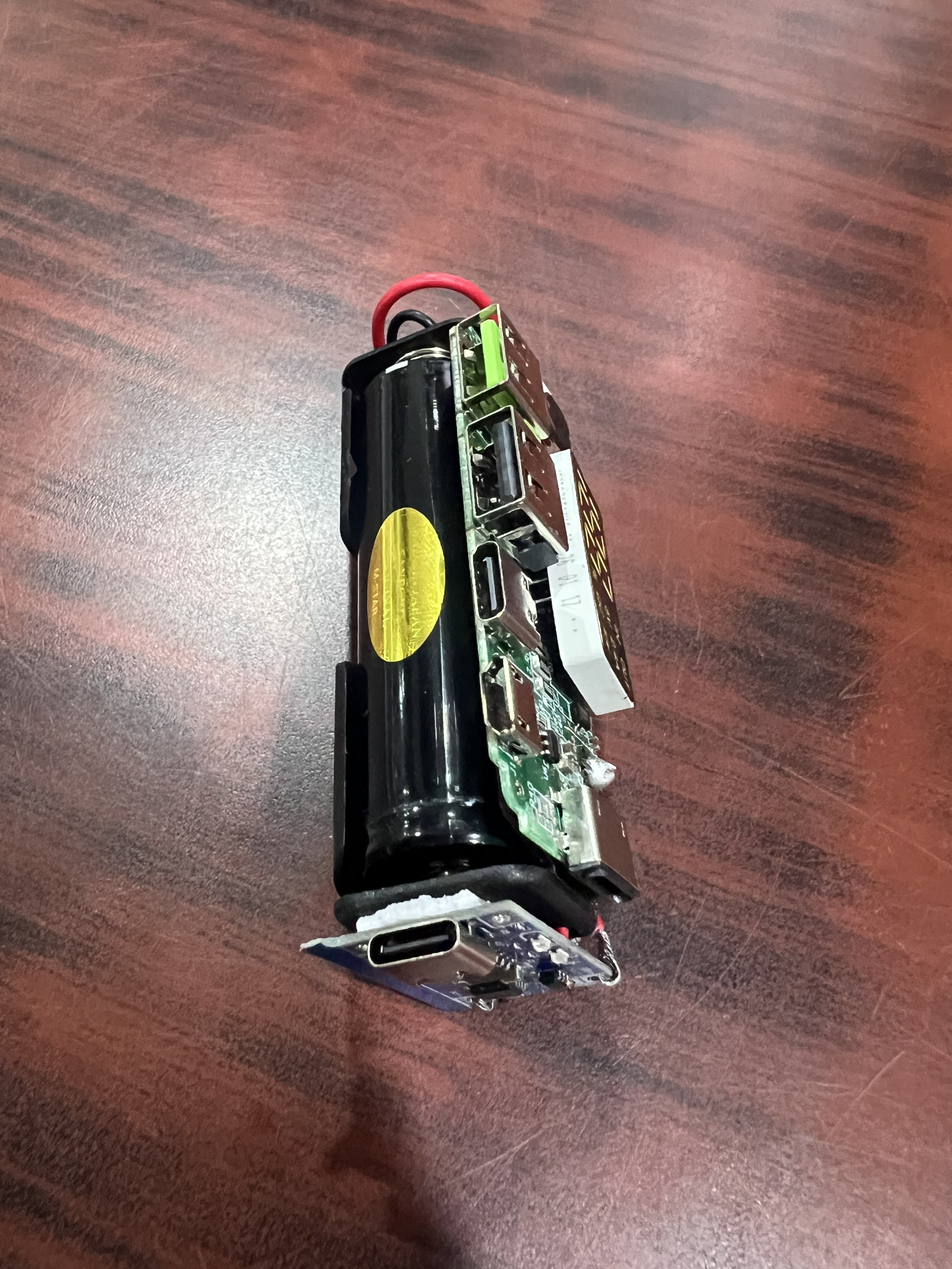
  • A disassembled power bank module on a wooden surface: a black cylindrical battery cell in a plastic bracket wired to a green board with two USB-A ports, and a small blue board with a USB-C connector.
    RECHARGABLE POWER BANK MODULE
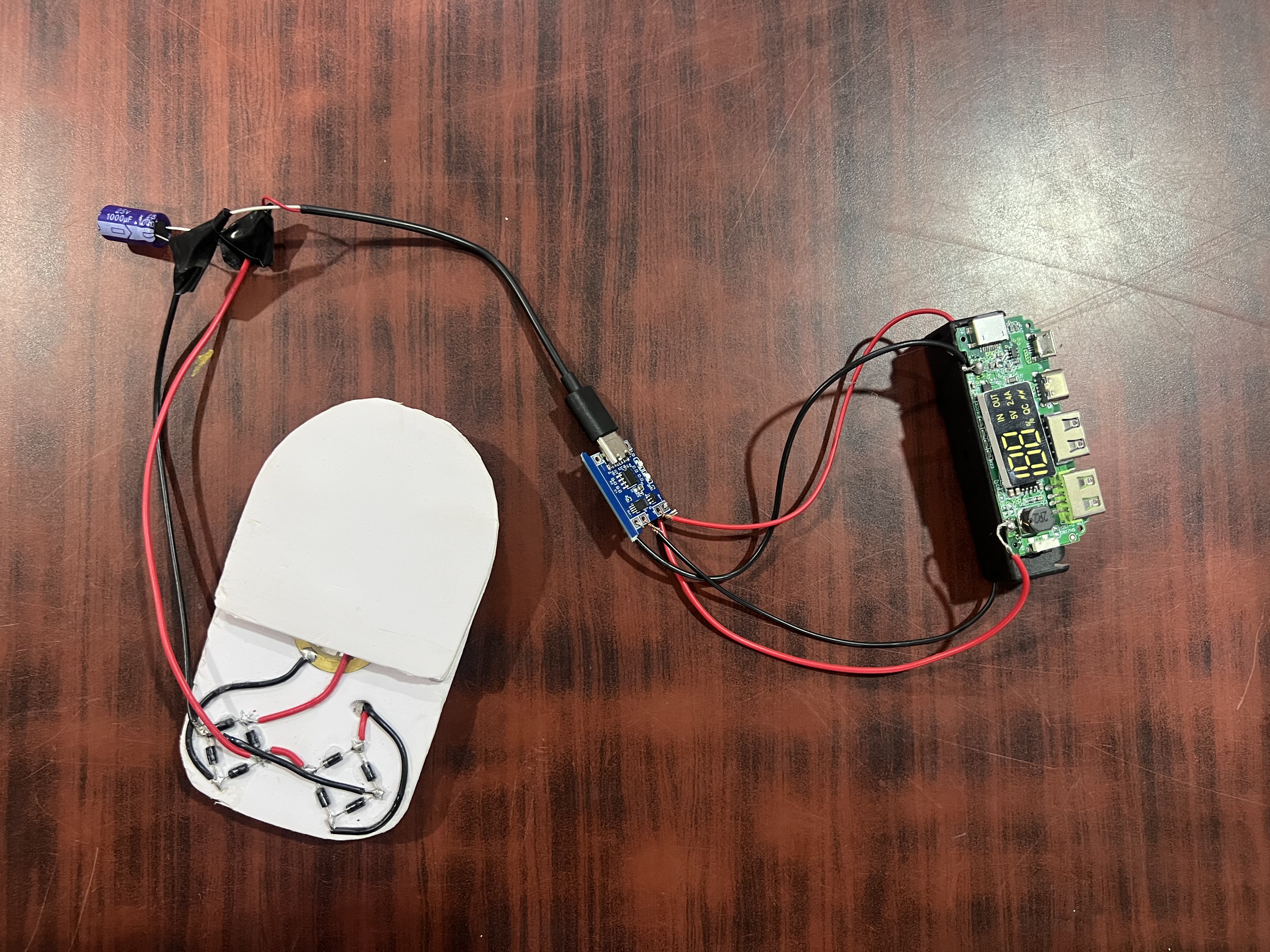
  • The white base wired through a blue capacitor marked 25V 1000µF to a small blue circuit board and a green power bank board whose display reads 100.
    FINAL CIRCUIT
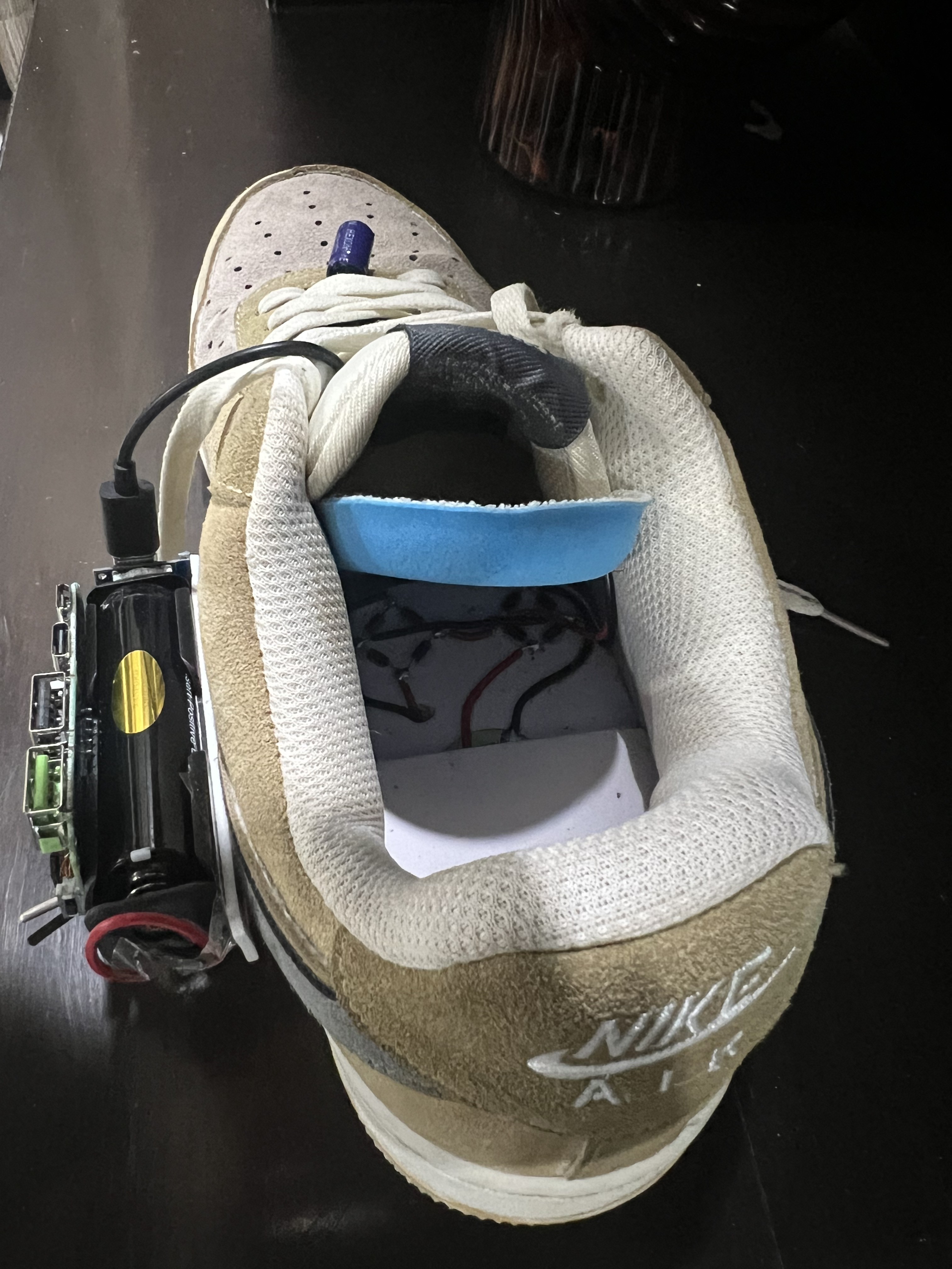
  • Inside a tan suede Nike sneaker with the blue insole lifted to show wires and solder joints in the footbed, the battery and circuit board mounted along the outside.
    INSIDE THE PROTOTYPE
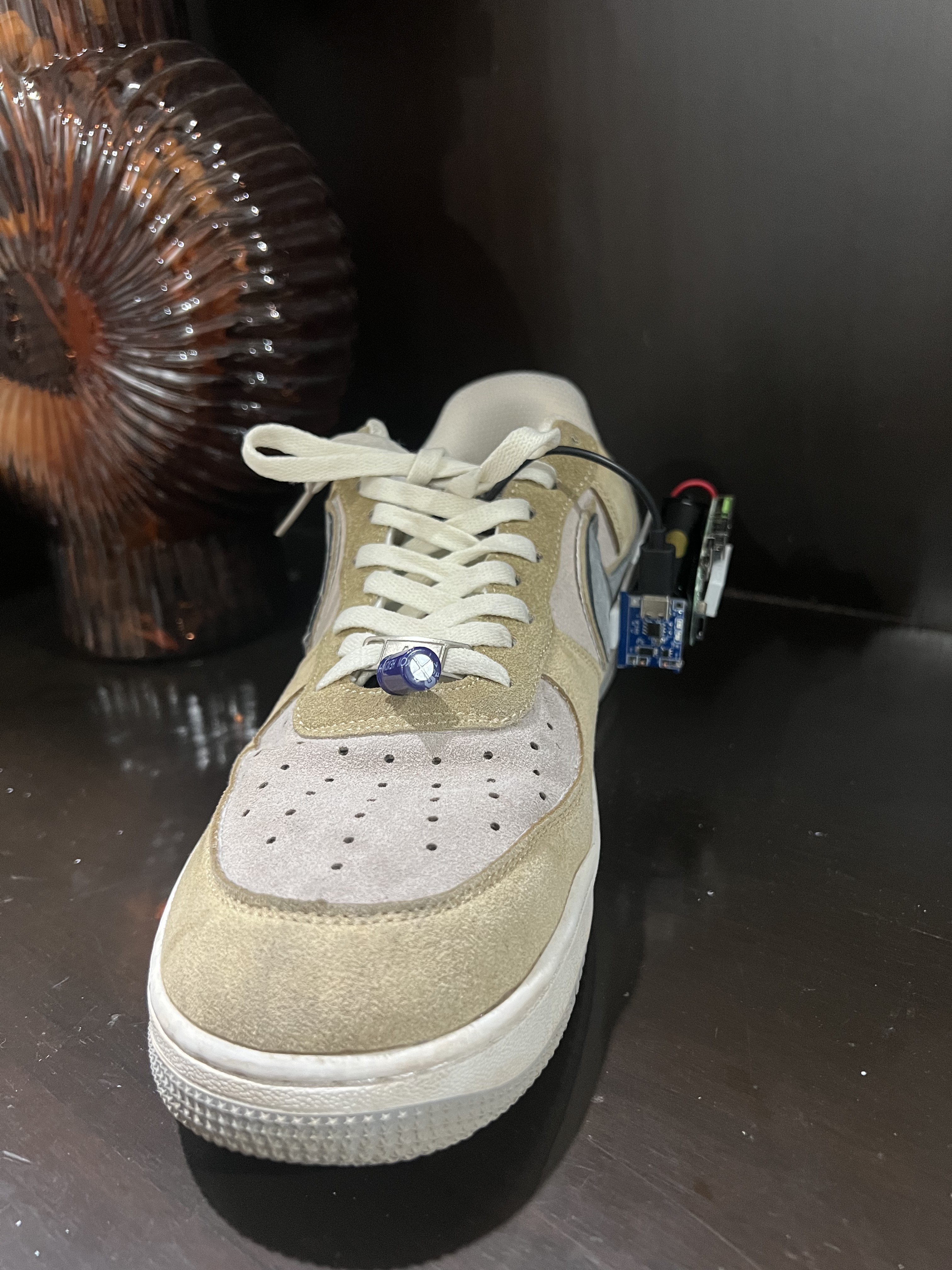
  • Front view of the finished sneaker with the blue capacitor clipped across the lowest laces and the circuit board protruding from the outer side.
    PROTOTYPE
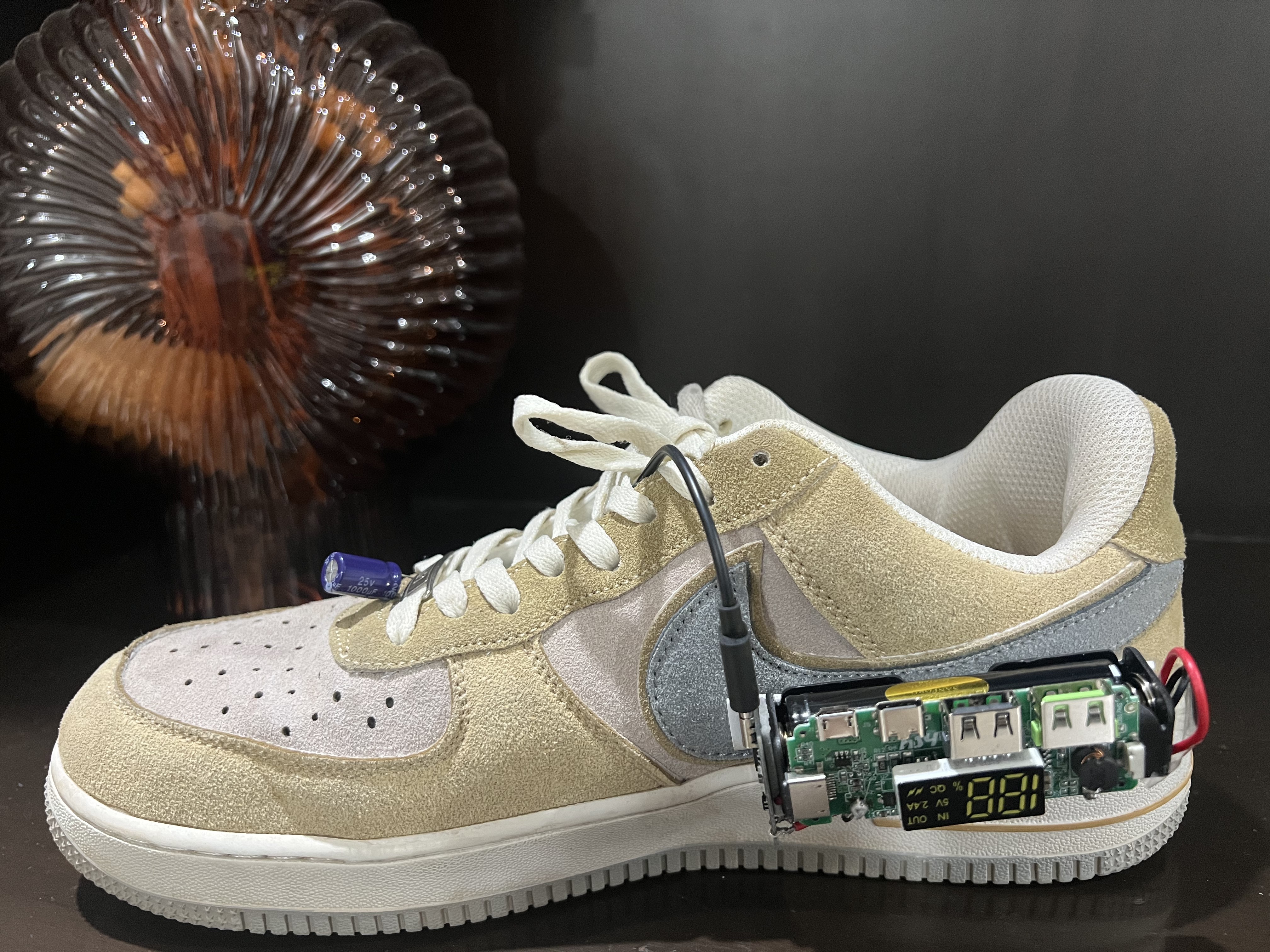
  • Side view of the finished sneaker on a dark surface: a blue capacitor laced across the toe, the power bank board mounted at the heel with its display lit at 100.
    PROTOTYPE